Parallel Robotics · Failure Recovery · UBC M.Eng

Spherical Parallel Manipulator

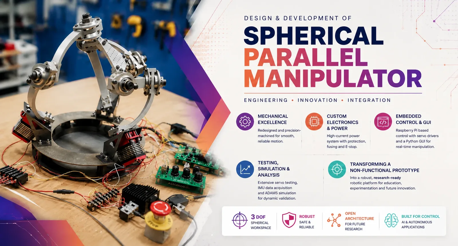
I was handed a self-locking robot skeleton: no motors, no electronics, no control system. I diagnosed why it wouldn't move, rebuilt the mechanism, re-engineered the actuation and power, and brought it to a fully controlled 3-DOF platform.

Root-Cause Analysis Actuator Sizing & Validation Power Electronics Sheet-Metal Design FEA Raspberry Pi Python GUI Android App Inverse Kinematics MSC Adams
The rebuilt Spherical Parallel Manipulator on the bench, with servo drives, power electronics and emergency stop
3-DOF
Spherical parallel robot
~60%
Of rated servo torque, measured on my test rig
2.5×
Design safety factor that absorbed it
3
Control modes: manual, desktop, Android

Engineering Snapshot.

Challenge

A spherical parallel manipulator from a previous capstone team at UBC's Machine Dynamics Lab came to me as a bare frame. The motors were gone and the electronics were gone, after the DC motors and the controllers had failed in the earlier build. The structure itself bound up and wouldn't move freely.

My Role

Sole engineer on the recovery, under the supervision of Dr. Ahmad Mohammadpanah. I handled diagnosis, mechanical rework, actuator sizing and testing, power-system design, mount and base redesign with FEA, all fabrication (self-supervised at UBC Makerspaces), control electronics, the Android app, and the kinematic modelling. The original frame geometry was the previous team's design.

Systems

3-RRR spherical mechanism; Hitec HS-1100WP servos; a 24 V → 12 V DC/DC power rail with e-stop and per-servo fusing; Raspberry Pi 4 + PCA9685 PWM driver (I2C); potentiometer manual controllers; a Python desktop GUI; an Android app over Bluetooth; WIT-motion IMU; MSC Adams.

Outcome

A fully working 3-DOF platform. It moves freely with zero geometric binding, runs on load-validated actuators behind a protected power system, and is controlled three ways: manually with potentiometers, from a Python desktop GUI, and remotely from an Android app, with inverse-kinematics-driven preset orientations.

Skeleton to Platform.

Step 01 — Diagnosis

What I Inherited.

Not a broken robot. Not a partly working prototype. A mechanical skeleton.

The previous build had used DC motors driven by Arduinos. The motors burnt out, the controllers were damaged, and by the time the robot reached me the motors and electronics were gone. What was left was a frame that bound up under its own geometry. The arms had to be pulled together to assemble the platform, and that preload went straight into the joints.

From the handover and the earlier team's documentation, I traced each failure to its root cause before touching anything:

Symptom in the previous buildRoot causeWhat I did
DC motors burnt out The motors were never tested against the real load. Undersized for the torque, they drew current until they failed. Re-derived the torque budget from measured mass. Chose servos with a 2.5× safety factor, then bench-tested them.
Arduino and electronics destroyed No decoupling between the logic and motor-power circuits. Separated the rails: a dedicated 12 V servo bus, an isolated 5 V logic supply, an e-stop, a 30 A main fuse and a 6 A fuse per servo.
Limit switches tripped only after the arm reached singularity The switch placement defeated their purpose. Removed them. Servo endpoints are set in the controllers and software to stop before singularity.
Frame bound up; play at the hubs Assembly misalignment and preload across the joints. Rebuilt the mechanism on free bearings and spindles first (Step 02).
Lag between command and motion Laptop → Arduino serial latency. Moved control onto a Raspberry Pi 4 driving the servos directly over I2C.
Step 02 — Mechanism

Fix the Mechanism First.

A parallel manipulator that fights itself will destroy any actuator you bolt onto it. That's very likely part of what happened to the original motors. So I didn't buy anything yet.

I stripped the frame down and rebuilt it on free bearings and spindles: studs and bearing sleeves I designed and turned on the lathe, bearing surfaces cut to tolerance and finished at 2000 grit, and flats milled for the hubs. I re-assembled the arms and corrected the misalignment until the platform went together with no force and every degree of freedom swung freely by hand.

Machined shaft, shaft in base mount, bearing-stud assembly and the full SPM subassembly, with the lathe and milling machine used
Lathe-turned studs and bearing sleeves let me test the bare mechanism by hand and remove the binding before choosing actuators.
Manual test after the rebuild: free motion through the workspace, zero geometric binding.
The hand test

No motors, no electronics: just the bare mechanism moved by hand. I confirmed each degree of freedom moved independently and smoothly through the workspace.

Only when the mechanism moved cleanly on its own did I size actuators for it.

You don't add actuation to a broken mechanism. You fix the mechanism first.

Step 03 — Actuation

Size the Actuator, Then Prove It.

I sized from measured numbers, not the old spec. The moving assembly weighed 4.124 kg; I budgeted 5 kg to leave room for sensors. Three actuators share the load, so each carries 1.67 kg acting at 250 mm. That works out to ~4.1 N·m (41 kg·cm). With a 2.5× safety factor I needed ≥102 kg·cm and ≥3.34 rad/s. After benchmarking five large-scale servos, I chose the Hitec HS-1100WP (rated 110 kg·cm). Its built-in position control also removed the backlash and limit-switch problems of the old DC motors.

Then I didn't trust the datasheet. I built a test rig: the servo on an aluminium swing arm with load points at 143, 285 and 485 mm, loads from 1.35 to 2.2 kg, a 12–14.8 V supply, and current logged at every point.

The servo delivered about 65 kg·cm, roughly 60% of its rating, and raising the voltage didn't change it. At the real working radius it still held 2.2 kg at 285 mm against a 1.66 kg requirement. The 2.5× margin I'd designed in is the only reason the design survived an underperforming part. One servo failed under deliberate overload despite a bench current limit, which is why every channel on the robot now has its own fuse.

That habit comes from regulated manufacturing: you don't assume a component meets spec, you verify it.

Servo validation rig: weights at fixed radii, current logged at each point. Measured torque came out about 60% of the rated value.
Servo bench test: hold status and current draw at 12 V
Load radius1.35 kg1.61 kg1.81 kg2.2 kg
143 mm Pass0.6 A Pass0.8 A Pass1.1 A Pass1.2 A
285 mm Pass1.3 A Pass1.6 A Pass1.8 A Pass2.0 A
485 mm Pass1.6 A Fail2.5 A Fail3.7 A Fail4.0 A

Rated 110 kg·cm → should hold 2.26 kg at 485 mm. Actual max: 1.35 kg → ~65 kg·cm. Working requirement: 1.66 kg at ~280 mm, so a measured margin of ~1.3×.

Step 04 — Structure

Redesign the Base and Make It.

Swapping DC motors for servos wasn't a component swap. The servos have a different form factor, mounting pattern and position relative to the joint axis, and the servo bodies dug into the original base plate. I redesigned the servo mounts in 1.4 mm sheet steel while holding the original mounting plane and hub position, so the kinematic geometry stayed unchanged. FEA put the mount at a safety factor of about 15 with roughly 0.1 mm maximum deflection. I re-cut the base plate for clearance and re-checked it in FEA.

I did all the fabrication myself, self-supervised, at UBC Makerspaces:

  • shearing and waterjet cutting (DXF → toolpath) for the sheet-metal mounts
  • a 24-ton press brake, using locating tabs I designed into the flat pattern
  • the lathe for non-standard 16 mm ID / 20 mm OD / 1.2 mm spacers that keep each arm in its original position
  • drilling and tapping to re-pattern the arm hubs for the servo horns
FEA results for the modified base plate and modified servo mount: principal stresses, safety factor, von Mises stress and total displacement
FEA on the redesigned base plate and servo mount: safety factor of about 15 and roughly 0.1 mm maximum deflection on the mount.
Fabrication sequence: waterjet toolpath, waterjet cutting, cut sheet-metal parts, hydraulic press brake, bending and finished servo mounts
Servo mounts: waterjet-cut, formed on the press brake, and FEA-checked before cutting metal.
Step 05 — Power

Power It Safely, Then Watch It Move.

The original electronics died because motor power and logic weren't separated, so the power system came first. Worst case is about 6 A per servo, roughly 20 A for the bus. I reused the 24 V / 300 W adapter from the earlier build through a 96%-efficient 24 → 12 V DC/DC converter, which gives about 24 A available. The chain is: e-stop → 30 A main fuse → DC/DC → a 6 A fuse on each servo. The logic side (servo driver, manual controllers) runs on its own 5 V supply, so a motor fault can't reach the ICs.

Servo power supply hardware and schematic: 24 V supply, emergency stop, 30 A fuse, 24 to 12 V DC/DC converter, 6 A fuse per servo, plus the manual potentiometer controllers
Power chain: e-stop → 30 A main fuse → 24 → 12 V DC/DC → a 6 A fuse per servo, with the manual controllers on their own supply.
The rebuilt SPM running: servo actuation, Raspberry Pi control, smooth motion across the hemispherical workspace.
First motion

Then I connected everything, ran the control script, and watched the platform move for the first time.

Step 06 — Control

Control It Three Ways, and Model It.

  • Manual: potentiometer servo controllers with programmable endpoints. I used them to find the singularity limits physically and lock them out.
  • Desktop: a Python GUI running on the Raspberry Pi 4, which drives the servos through a 16-channel PCA9685 PWM driver over I2C. It has per-motor angle sliders, calibration, stop/go control and preset demo motions.
  • Remote: I built an Android app that talks to the Pi over Bluetooth, with per-joint angle sliders, calibration, and preset positions.
  • Kinematics: with the guidance of Dr. Ahmad Mohammadpanah, I developed the inverse kinematics and an MSC Adams dynamic model of the mechanism, which gives the actuator torque profiles across a motion cycle. The app's preset orientations run through the IK solution, which turns a target platform orientation into the three joint angles.
  • Instrumentation: a WIT-motion IMU on the platform logged acceleration, angular rate and orientation during test runs.
SPM control system: desktop control panel with per-motor sliders, Android servo-control app, and the Raspberry Pi with PCA9685 servo driver
Control layer: per-joint angle control and IK-driven preset orientations, driving the servos through the Raspberry Pi.

What This Proves.

The interesting problems aren't the ones you design from a clean sheet. They're the ones where someone hands you hardware that doesn't work, with no clear reason why, and asks you to make it work. That takes diagnosis, structured reasoning, and the discipline to fix the root cause before adding complexity. It's the same thinking I've applied to Class III medical devices, construction robotics and prosthetics.

What I'd do next
  • Non-contact encoders at each joint for true closed-loop position control. Today the servos' internal loops are the only feedback.
  • Move singularity limits fully into the IK layer.
  • Autonomous path planning across the hemispherical workspace (A* / RRT with depth and proximity sensing).

Credits.

Supervised by Dr. Ahmad Mohammadpanah, Machine Dynamics Lab, UBC. Original frame designed by a previous UBC capstone team. Fabrication at UBC Makerspaces.

Failure Diagnosis Root-Cause Analysis Torque & Actuator Sizing Test-Rig Design Power Distribution & Protection Sheet-Metal Design FEA Lathe / Mill / Waterjet / Press Brake Raspberry Pi I2C / PWM Python GUI Android App Inverse Kinematics MSC Adams IMU Instrumentation

Got hardware that won't work?

Prototypes that won't move, mechanisms that bind, electronics that keep failing. Finding out why and fixing it is the work I do. Tell me what's stuck.